原理を理解するために全天球画像画像からの変換のPythonコードを色々作ってみましたが、整理して関数として使えるようにしました。理屈はいいから使いたい。という方はこちらをどうぞ。理屈が知りたい方は過去の記事をご参照ください。
OpenCVに装備されててもよさそうなものですが、どうもなさそうなので自作です。Pythonのライブラリはありそうですが。
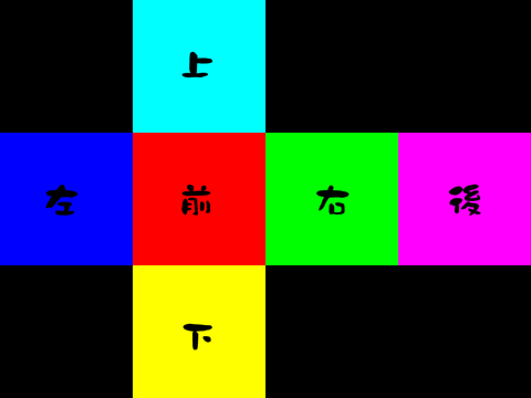
全体像
全天球画像もしくはCubeMapから自由視点での画像切り出しを目的に作りました。一般的なビューアーで見られる画像は作れるのではないかと思います。
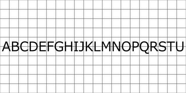
こんな全天球画像や
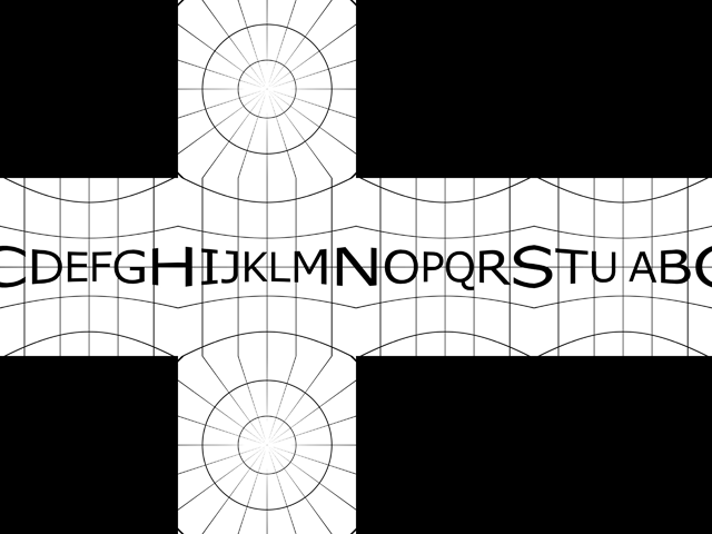
こんなCubeMapから
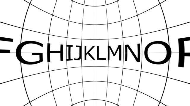
こんな画像を切り出すものです。
また全天球画像もしくはCubeMapへの書き出しもできるようにしました。
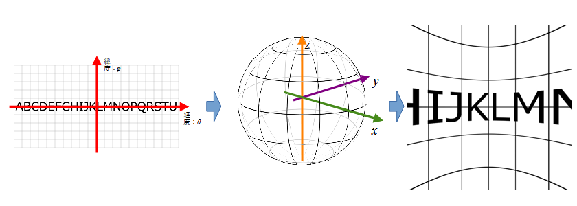
基本思想としては3次元座標x,y,zを介してマッピングをしています。全天球画像→(x,y,z)→2次元座標となるようにしています。視点はx,y,zから変換することで切り替えています。回転はこの3次元座標で行っています。
保存時に360度画像だよ~ってタグをつけてはいないのでそのあたりは何とかしてください。
コード
コピペしてください。OpenCVが必要です。moduleとして外だしするのがクールだと思いますがひとまずベタベタに羅列。
import numpy as np
import cv2


##
# @brief 3次元座標群取得関数
# @details 360度画像の緯度経度が半径1の球の3次元座標のどこにマッピングされるか
# @param img_w 360度画像の幅
# @param img_h 360度画像の高さ
# @return x,y,zの座標群
def create_3dmap_for_equirectangular(img_w, img_h):

    h = np.linspace(-np.pi/2, np.pi/2, img_h, endpoint=False)
    w = np.linspace(-np.pi, np.pi, img_w, endpoint=False)

    # 配列を対称形にするためのオフセット
    h = h + (np.pi/2) / img_h
    w = w + np.pi / img_w

    theta, phi = np.meshgrid(w, h)

    x = np.cos(phi) * np.cos(theta)
    y = np.cos(phi) * np.sin(theta)
    z = np.sin(phi)

    return x, y, z


##
# @brief 3次元座標群切り出し関数
# @details とある視点からとある距離の平面を通る半径1の球の表面を結んだ交点座標群を切り出す
# @param img_w 画像の幅(分解能)
# @return x,y,zの座標群
def create_3dmap_for_cube(img_w):

    senser_w = 0.5

    w = np.linspace(-senser_w, senser_w, img_w, endpoint=False)
    h = np.linspace(-senser_w, senser_w, img_w, endpoint=False)

    # 配列を対称形にするためのオフセット
    w = w + senser_w / img_w
    h = h + senser_w / img_w

    # センサの座標
    ww, hh = np.meshgrid(w, h)

    # 直線の式
    a1 = 2 * ww
    a2 = 2 * hh

    # 球面上の3次元座標
    x = (1 / (1 + a1**2 + a2**2)) ** (1/2)
    y = a1 * x
    z = a2 * x

    return x, y, z


##
# @brief 3次元座標群切り出し関数
# @details とある視点からとある距離の平面を通る半径1の球の表面を結んだ交点座標群を切り出す
# @param img_w 画像の幅(分解能)
# @param img_h 画像の高さ(分解能)
# @param senser_size センサに見立てた平面の大きさ(0以上の少数)
# @param view_point 視点位置
# @param senser_point 視点から平面までの距離
# @return x,y,zの座標群
def create_3dmap_from_viewpoint(img_w, img_h, senser_size, view_point, senser_point):

    senser_w = senser_size
    senser_h = senser_size * img_h / img_w

    x1 = view_point   # 視点の位置
    x2 = view_point + senser_point  # 撮像面の位置(必ず視点より前)

    w = np.linspace(-senser_w, senser_w, img_w, endpoint=False)
    h = np.linspace(-senser_h, senser_h, img_h, endpoint=False)

    # 配列を対称形にするためのオフセット
    w = w + senser_w / img_w
    h = h + senser_h / img_h

    # センサの座標
    ww, hh = np.meshgrid(w, h)

    # 直線の式
    a1 = ww / (x2 - x1)
    a2 = hh / (x2 - x1)
    b1 = -a1 * x1
    b2 = -a2 * x1

    a = 1 + a1**2 + a2**2
    b = 2 * (a1 * b1 + a2 * b2)
    c = b1**2 + b2**2 - 1

    d = (b**2 - 4*a*c) ** (1/2)

    # 球面上の3次元座標
    x = (-b + d) / (2 * a)
    y = a1 * x + b1
    z = a2 * x + b2

    return x, y, z


##
# @brief 3次元回転座標を取得する関数
# @details 3次元座標群を原点から指定された角度で回転させる
# @param x x座標群
# @param y y座標群
# @param z z座標群
# @param roll roll角(度単位)
# @param pitch pitch角(度単位)
# @param yaw yaw角(度単位)
# @return 回転後の3次元座標
def rotate_3dmap(x, y, z, roll, pitch, yaw):

    # 回転量
    roll = np.deg2rad(roll)
    pitch = np.deg2rad(pitch)
    yaw = np.deg2rad(yaw)

    # 3次元の回転行列
    mtx1 = np.array([[1, 0, 0],
                     [0, np.cos(roll), np.sin(roll)],
                     [0, -np.sin(roll), np.cos(roll)]])

    mtx2 = np.array([[np.cos(pitch), 0, -np.sin(pitch)],
                     [0, 1, 0],
                     [np.sin(pitch), 0, np.cos(pitch)]])

    mtx3 = np.array([[np.cos(yaw), np.sin(yaw), 0],
                     [-np.sin(yaw), np.cos(yaw), 0],
                     [0, 0, 1]])

    # 回転行列の積
    mtx4 = np.dot(mtx3, np.dot(mtx2, mtx1))

    # 座標の行列計算
    xd = mtx4[0][0] * x + mtx4[0][1] * y + mtx4[0][2] * z
    yd = mtx4[1][0] * x + mtx4[1][1] * y + mtx4[1][2] * z
    zd = mtx4[2][0] * x + mtx4[2][1] * y + mtx4[2][2] * z

    return xd, yd, zd


##
# @brief 緯度経度情報にしたがって画像を変換する関数
# @details 1:2で格納されている画像から、そのx,y座標を緯度経度と見立てて対応する座標変換を行う
# @param img 元となる360度画像(1:2)
# @param x x座標群
# @param y y座標群
# @param z z座標群
# @return 変換された画像
def remap_from_equirectangular(img, x, y, z, interpolation=cv2.INTER_CUBIC, borderMode=cv2.BORDER_WRAP):

    # 緯度・経度へ変換
    phi = np.arcsin(z)
    theta = np.arcsin(np.clip(y / np.cos(phi), -1, 1))

    theta = np.where((x<0) & (y<0), -np.pi-theta, theta)
    theta = np.where((x<0) & (y>0),  np.pi-theta, theta)

    img_h, img_w = img.shape[:2]

    # 画像座標へ正規化(座標を画素位置に戻すため0.5オフセット)
    phi = (phi * img_h / np.pi + img_h / 2).astype(np.float32) - 0.5
    theta = (theta * img_w / (2 * np.pi) + img_w / 2).astype(np.float32) - 0.5

    return cv2.remap(img, theta, phi, interpolation, borderMode = borderMode)


##
# @brief 全天球画像からキューブ画像を作る
# @details 半径1の球の中の1辺1の立方体に画像をマッピングさせ、6面を展開図として張り付ける
# @param img 元となる360度画像(1:2)
# @param width 1面の幅
# @return 変換された画像
def equirectangular_to_cube(img, width, interpolation=cv2.INTER_CUBIC):

#    x, y, z = create_3dmap_from_viewpoint(width, width, 0.5, 0, 0.5)
    x, y, z = create_3dmap_for_cube(width)

    front = remap_from_equirectangular(img, x, y, z, interpolation)

    x1, y1, z1 = rotate_3dmap(x, y, z, 0, 0, -90) # 球を左90度まわす
    right = remap_from_equirectangular(img, x1, y1, z1, interpolation)

    x1, y1, z1 = rotate_3dmap(x, y, z, 0, 0, 90)
    left = remap_from_equirectangular(img, x1, y1, z1, interpolation)

    x1, y1, z1 = rotate_3dmap(x, y, z, 0, 0, 180)
    back = remap_from_equirectangular(img, x1, y1, z1, interpolation)

    x1, y1, z1 = rotate_3dmap(x, y, z, 0, 90, 0) # 球を上90度まわす(正面に下が来る)
    bottom = remap_from_equirectangular(img, x1, y1, z1, interpolation)

    x1, y1, z1 = rotate_3dmap(x, y, z, 0, -90, 0)
    up = remap_from_equirectangular(img, x1, y1, z1, interpolation)

    # 背景となる画像
    canvas = np.zeros((width*3, width*4, img.shape[2]), dtype=img.dtype)

    canvas[width*1:width*2,        :width*1] = left
    canvas[width*1:width*2, width*1:width*2] = front
    canvas[width*1:width*2, width*2:width*3] = right
    canvas[width*1:width*2, width*3:       ] = back
    canvas[       :width*1, width*1:width*2] = up
    canvas[width*2:       , width*1:width*2] = bottom

    return canvas


##
# @brief cube画像にのりしろをつける
# @details 画素補間用にcube画像の境界部に2画素分反対側の画像を付与する
# @param img cube画像
# @return のりしろ付き画像
def add_norishiro_to_cube(img):

    h,w,c = img.shape
    cw = w // 4

    # 周囲2画素大きい画像を用意
    canvas = np.zeros((h+4, w+4, c), dtype=img.dtype)
    canvas[2:-2, 2:-2,:] = img

    # 上下左右にのりしろをつける
    # up
    canvas[0:2,cw+2:2*cw+2,:] = np.rot90(img[cw:cw+2, 3*cw:,:], 2)
    # bottom
    canvas[-2:,cw+2:2*cw+2,:] = np.rot90(img[2*cw-2:2*cw,3*cw:,:], 2)
    # left
    canvas[cw+2:2*cw+2,0:2,:] = img[cw:2*cw,-2:,:]
    # right
    canvas[cw+2:2*cw+2,-2:,:] = img[cw:2*cw,0:2,:]

    # 残りの折り返しの部分のコピー
    canvas[cw:cw+2,:cw+2,:] = np.rot90(canvas[:cw+2,cw+2:cw+4,:])
    canvas[:cw+2,cw:cw+2,:] = np.rot90(canvas[cw+2:cw+4,:cw+2,:],3)
    #
    canvas[2*cw+2:2*cw+4,:cw+2,:] = np.rot90(canvas[2*cw+2:,cw+2:cw+4,:],3)
    canvas[2*cw+2:,cw:cw+2,:] = np.rot90(canvas[2*cw:2*cw+2,:cw+2,:])
    #
    canvas[cw:cw+2,2*cw+2:3*cw+2,:] = np.rot90(canvas[2:cw+2,2*cw:2*cw+2,:],3)
    canvas[:cw+2,2*cw+2:2*cw+4:] = np.rot90(canvas[cw+2:cw+4,2*cw+2:3*cw+4,:])
    #
    canvas[2*cw+2:2*cw+4,2*cw+2:3*cw+2,:] = np.rot90(canvas[2*cw+2:-2,2*cw:2*cw+2,:])
    canvas[2*cw+2:,2*cw+2:2*cw+4,:] = np.rot90(canvas[2*cw:2*cw+2,2*cw+2:3*cw+4,:], 3)

    #
    canvas[cw:cw+2, 3*cw+2:,:] = canvas[3:1:-1, 2*cw+1:cw-1:-1,:]
    canvas[2*cw+2:2*cw+4, 3*cw+2:,:] = canvas[-3:-5:-1, 2*cw+1:cw-1:-1,:]

    return canvas


##
# @brief キューブ画像を元に画像を変換する。
# @details 6面を展開図から変換
# @param img 元となるキューブ(展開図)画像
# @param x x座標群
# @param y y座標群
# @param z z座標群
# @return 変換された画像
def remap_from_cube(img, x, y, z, interpolation=cv2.INTER_CUBIC):

    width = img.shape[1] // 4
    w = 0.5

    # front
    xx = w*y / x + w
    yy = w*z / x + w
    mask = np.where((xx > 0) & (xx < 1) & (yy > 0) & (yy < 1) & (x > 0), 1, 0)
    tmpx = np.where(mask, xx*width + width, 0)
    tmpy = np.where(mask, yy*width + width, 0)

    # back
    xx = w*y / x + w
    yy = -w*z / x + w
    mask = np.where((xx > 0) & (xx < 1) & (yy > 0) & (yy < 1) & (x < 0), 1, 0)
    tmpx = np.where(mask, xx*width + width*3, tmpx)
    tmpy = np.where(mask, yy*width + width, tmpy)

    #right
    xx = -w*x / y + w
    yy = w*z / y + w
    mask = np.where((xx > 0) & (xx < 1) & (yy > 0) & (yy < 1) & (y > 0), 1, 0)
    tmpx = np.where(mask, xx*width + width*2, tmpx)
    tmpy = np.where(mask, yy*width + width, tmpy)

    #left
    xx = -w*x / y + w
    yy = -w*z / y + w
    mask = np.where((xx > 0) & (xx < 1) & (yy > 0) & (yy < 1) & (y < 0), 1, 0)
    tmpx = np.where(mask, xx*width, tmpx)
    tmpy = np.where(mask, yy*width + width, tmpy)

    #up
    xx = -w*y / z + w
    yy = -w*x / z + w
    mask = np.where((xx > 0) & (xx < 1) & (yy > 0) & (yy < 1) & (z < 0), 1, 0)
    tmpx = np.where(mask, xx*width + width, tmpx)
    tmpy = np.where(mask, yy*width, tmpy)

    #bottom
    xx = w*y / z + w
    yy = -w*x / z + w
    mask = np.where((xx > 0) & (xx < 1) & (yy > 0) & (yy < 1) & (z > 0), 1, 0)
    tmpx = np.where(mask, xx*width + width, tmpx)
    tmpy = np.where(mask, yy*width + width*2, tmpy)

    cube = add_norishiro_to_cube(img)

    # のりしろ2画素と座標を画素位置に戻すため0.5オフセット
    tmpx += (2.0 - 0.5)
    tmpy += (2.0 - 0.5)

    return cv2.remap(cube, tmpx.astype(np.float32), tmpy.astype(np.float32), interpolation)


##
# @brief キューブ画像から全天球画像を作る
# @details 6面を展開図から全天球画像へ変換する
# @param img 元となるキューブ(展開図)画像
# @param width 全天球画像の幅(2の倍数である必要がある)
# @return 変換された画像
def cube_to_equirectangular(img, width, interpolation=cv2.INTER_CUBIC):

    img_w = width
    img_h = width // 2
    width = img.shape[1] // 4

    x, y, z = create_3dmap_for_equirectangular(img_w, img_h)

    return remap_from_cube(img, x, y, z, interpolation)
コメント込みでも350行。
使い方その1 視点の回転
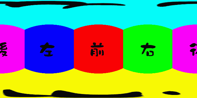
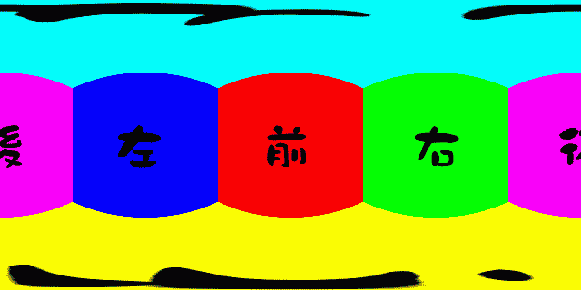
首を左右に振る。上下に振る。首を傾げる。の3方向。rotate_3dmapに与える角度を変えるだけです。
ソース画像はこれ。もちろん全天球画像(エクイレクタングラー画像)でも同じように扱えます。
cube = cv2.imread("color_cube.png")
x, y, z = create_3dmap_for_equirectangular(640, 320)

for i in range(10):
    ofile = os.path.join("\ani", 'cube_{0:03d}.png'.format(i+1))
    out = remap_from_cube(cube, x, y, z)
    cv2.imwrite(ofile, out)
    x, y, z = rotate_3dmap(x, y, z, 5, 0, 0)

for i in range(10):
    ofile = os.path.join("\ani", 'cube_{0:03d}.png'.format(i+10))
    out = remap_from_cube(cube, x, y, z)
    cv2.imwrite(ofile, out)
    x, y, z = rotate_3dmap(x, y, z, -5, 0, 0)

上下(ピッチ)
左右(ヨー)
首傾げ(ロール)
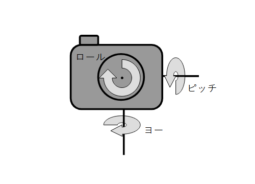
ヨー・ピッチ・ロールの意味合いとしてはこんな感じ。
使い方その2 ズームと前進
とある視点から見えている画像をズームする。とある視点から前進する。似てますが微妙に効果が違います。
ズーム
cube = cv2.imread("color_cube.png")
for i in range(40):
    x, y, z = create_3dmap_from_viewpoint(640, 480, 0.5 - i/100, -2.0, 0.5)
    ofile = os.path.join("\ani", 'cube_{0:03d}.png'.format(i+1))
    out = remap_from_cube(cube, x, y, z)
    cv2.imwrite(ofile, out)
前進
cube = cv2.imread("color_cube.png")
for i in range(40):
    x, y, z = create_3dmap_from_viewpoint(640, 480, 0.5, -2.0 + i/20, 0.5)
    ofile = os.path.join("\ani", 'cube_{0:03d}.png'.format(i+1))
    out = remap_from_cube(cube, x, y, z)
    cv2.imwrite(ofile, out)
結果

ズーム

前進
正面の正方形のゆがみ方が微妙に異なります。左右の壁の見え方も変わります。ズームはただ拡大しているだけですね。
まとめ
理屈はさておき360度画像を自在に操作できる気がしてきました。色々遊べそうです。
原理が知りてー。って方は
1.360度写真の平面投影
2.視点の変更と背面の投影
3.視点の回転
CubeMapの扱いは
1.全天球画像からCubeMap
2.CubeMapから全天球画像
原理はなんとなくわかったので頑張ればCでも書けそうです。
コメント